Menu toggle

vacuum line setup

rickware

New member
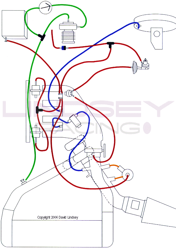
can anyone confirm if this diagram is the correct way to setup a 91 944turbo with lindsey dual port wastegate and a greddy electronic boost control? my vacuums seem to be different to those shown here which could be part of my problem with the car running rough between 2 - 3000 rpm


E12DD520D4C84619BD315A76AA9029A8.gif
 
If you're referring to the green line then that looks about right. On the Lindsay DPW the top port is the port that should be connected to the banjo bold and the DPW side port should be the 'control' line from the EBC solenoid/MBC.
 
Is it normal to regulate the boost pressure after the turbo but before the intercooler. The pressure drop that the intercooler causes will vary with the flow rate of air, off the top of my head I would say to regulate the pressure on the engine side of the intercooler. That is my perspective as a control systems engineer not from experience.
 
I tend to agree with Tom the wastegate is regulating the boost pressure that is going in to the engine the best point to measure that would be at the inlet manifold.
I need to suss out the plumbing when i fit my Tial DPW, MY 88 Turbo does not have the parts fitted to the N/S inner wing vacumn lines and what looks like an adjustable regulator of some description, the 86 car has this, any idea what it does ?
 
My question was more for the overall vacuum setup, I have plumbed in the wastegate as shown but my cars appear to be different from the fpr side to the klr. also my dump valve goes directly to the other regulator on the fuel rail (don't know name) and on this diagram it looks like they should be contected together.
 
The intake pressure is measured by the ECU from the intake manifold, which means whether the pressure line for the wastegate is before or after the intercooler doesn't make a difference.

 
What difference does it make where the ECU measures boost from? My understanding is that the only thing the ECU measures boost for is for overboost protection, a feature which is disabled in many aftermarket performance modifications. I don't think it has a role in regulating boost pressure or in injecting fuel.

Edit: Perhaps you meant the EBC?
 
The pressure sensor in the KLR is calibrated to measure intake pressure from the intake manifold.
The KLR controls boost with the cycling valve, and the original set up with the cycling valve actually works within the same principle as an aftermarket EBC (in single port mode), with the extra of controlling knock :
- In limp home mode, the KLR closes the function of pressure regulation and peak boost will be whatever the wastegate spring allows, which is much less than the peak pressure of ~0.7 bar of an original car.
- In case of knock the KLR uses the cycling valve to lower boost pressure to the point no more knock can be observed.

As the cycling valve is disabled when aftermarket chips are fitted, and whether it is replaced with a MBC or an EBC, we still monitor boost with a pressure measured from the intake manifold (aftermarket boost gauges are usually routed on the KLR pressure line), and being able to put a value on the pressure that is in the hard pipe is of no importance for actual boost regulation.
 
Thanks for the info. I agree the pressure in the hard pipe is of no concequence if the pressure being monitored for purposes of feedback control by the KLR or EBC is the intake manifold pressure.
 
thanks ttm for this as i wondered what a cycling valve did. i have now bypassed this with my lindsey wastegate set up and left the metal pipe end open and plugged the end to the intake. i thought this was the reason why i couldn't get more the 1 bar boost on the dyno but your explanation means i will have to look else where if i understand correctly. you are basically saying it doesn't do anything unless it thinks there is a knock problem if i understand correctly.
 
Limp home mode excluded, the cycling valve should be active all the time, and to be honest I don't understand precisely how the boost regulation of the original set up works in normal conditions.

The cycling valve has three connectors :
- pressure line from the hard pipe
- vacuum line from the J-boot
- pressure line to the wastegate

Is the cycling valve supposed to :
- reroute air from the hard pipe to the wastegate when reducing boost pressure is needed?
- reroute air from the hard pipe to the J-boot to reduce vacuum so the turbo can spool faster (boost ramp)?
 
In a standard wastegate doesn't the pressure supplied from the boost line open up the wastegate by pushing on the spring. You mentioned before that in limp mode the KLR stops the pressure regulation which means the boost pressure is purely based upon the spring rate which is less than the normal boost pressure. This suggests that the cycling valve is reducing the pressure in the line to the wastegate to stop it opening when it normally would. In fault mode it probably drives the wastegate directly from boost pressure with no bleed off resulting in the limp home boost level. When knock is detected it probably doesnt bleed off as much pressure. This should lower the boost a little bit and help stock knock.
 
As I understand it, in limp home mode the cycling valve will increase the pressure to the wastegate by routing the pressure coming from the hard pipe so the wastegate can open as early as possible.
In normal running conditions, and under wide open throtlle, the higher the boost, the less the pressure to the wastegate.
 
The cycling valve can't increase pressure so to speak, it can only reduce the pressure sent to the wastegate to below the pressure in the hard pipe. The highest pressure that can ever be sent to the wastegate is the boost pressure in the hardpipe, the lowest pressure would be the vacuum in the jboot. The cycling valve can vary that pressure at any point in between the two (within reason). Like you say in limp mode the pressure sent to the wastegate would be the pressure in the hard pipe. Under WOT high boost it would be bleeding off the pressure sent to the wastegate into the jboot to keep the wastegate closed.

All speculation but it seems to make sense.
 
Well yes it seems to make sense. I never thought hard about how the original set up worked but thanks to this thread I think I now understand it :)
One interesting detail is that the cycling valve can't bleed boost by itself and the wastegate does this job, which isn't the case with a dual port wastegate where a boost controller that vents air into the atmosphere is needed.
 
ORIGINAL: rickware

My question was more for the overall vacuum setup, I have plumbed in the wastegate as shown but my cars appear to be different from the fpr side to the klr. also my dump valve goes directly to the other regulator on the fuel rail (don't know name) and on this diagram it looks like they should be contected together.

The Fuel pressure regulator and the 'dampner' I think it is are supposed to be linked to the same line which runs from the intake manifold and on to the recircling valve (DV). Hope this helps.

Edit to say: Just looked at the diagram and that works too. I think it depends on how many bango thingies come out of your manifold. I had different no.'s on the different age turbo's I had.
 
ORIGINAL: TTM

Well yes it seems to make sense. I never thought hard about how the original set up worked but thanks to this thread I think I now understand it :)
One interesting detail is that the cycling valve can't bleed boost by itself and the wastegate does this job, which isn't the case with a dual port wastegate where a boost controller that vents air into the atmosphere is needed.

I thought a dual port wastegate worked pretty much the same way as the cycling valve. The only difference I can see is that the DPW works by counteracting the boost pressure working to open the valve by feeding pressure into the other side of the diaphragm. Whereas the cycling valve would seem to work by just changing the pressure that is trying to open the valve. I don't see what the point in the dual port wastegate actually is, not when you have a feedback controller in the loop anyway. Perhaps they give you better control somehow, maybe by allowing you to make one side of the diaphragm a vacuum.
 
I couldn't see either the point of a dual port wastegate until I fitted an electronic boost controller.
With a manual boost controller the car would sometimes show hiccups on light throttle with part boost, with the electronic unit set accordingly it doesn't anymore.
 
They are not rare and not necessarily ££££[;)] I have one with nowhere to go. I was going to put it on ebay as soon as I can clear out the spare room and get access to the cupboard it is in.

A DPW is a comparative device - it is comparing the pressure either side of the diaphragm.

I don't think the diagram is quite correct at the top of the thread. I thought the banjo bolt take-off is on the hardpipe that is the output of the IC i.e. between the IC output but before the throttle valve?
 

Posts made and opinions expressed are those of the individual forum members

Use of the Forum is subject to the Terms and Conditions

Disclaimer

The opinions expressed on this site are not necessarily those of the Club, who shall have no liability in respect of them or the accuracy of the content. The Club assumes no responsibility for any effects arising from errors or omissions.

Porsche Club Great Britain gives no warranties, guarantees or assurances and makes no representations or recommendations regarding any goods or services advertised on this site. It is the responsibility of visitors to satisfy themselves that goods and/or services supplied by any advertiser are bona fide and in no instance can the Porsche Club Great Britain be held responsible.

When responding to advertisements please ensure that you satisfy yourself of any applicable call charges on numbers not prefixed by usual "landline" STD Codes. Information can be obtained from the operator or the white pages. Before giving out ANY information regarding cars, or any other items for sale, please satisfy yourself that any potential purchaser is bona fide.

Directors of the Board of Porsche Club GB, Club Office Staff, Register Secretaries and Regional Organisers are often requested by Club members to provide information on matters connected with their cars and other matters referred to in the Club Rules. Such information, advice and assistance provided by such persons is given in good faith and is based on the personal experience and knowledge of the individual concerned.

Neither Porsche Club GB, nor any of the aforementioned, shall be under any liability in respect of any such information, advice or assistance given to members. Members are advised to consult qualified specialists for information, advice and assistance on matters connected with their cars at all times.

Back
Top